How do I test my PCB design? Which software is best?

Design verification:
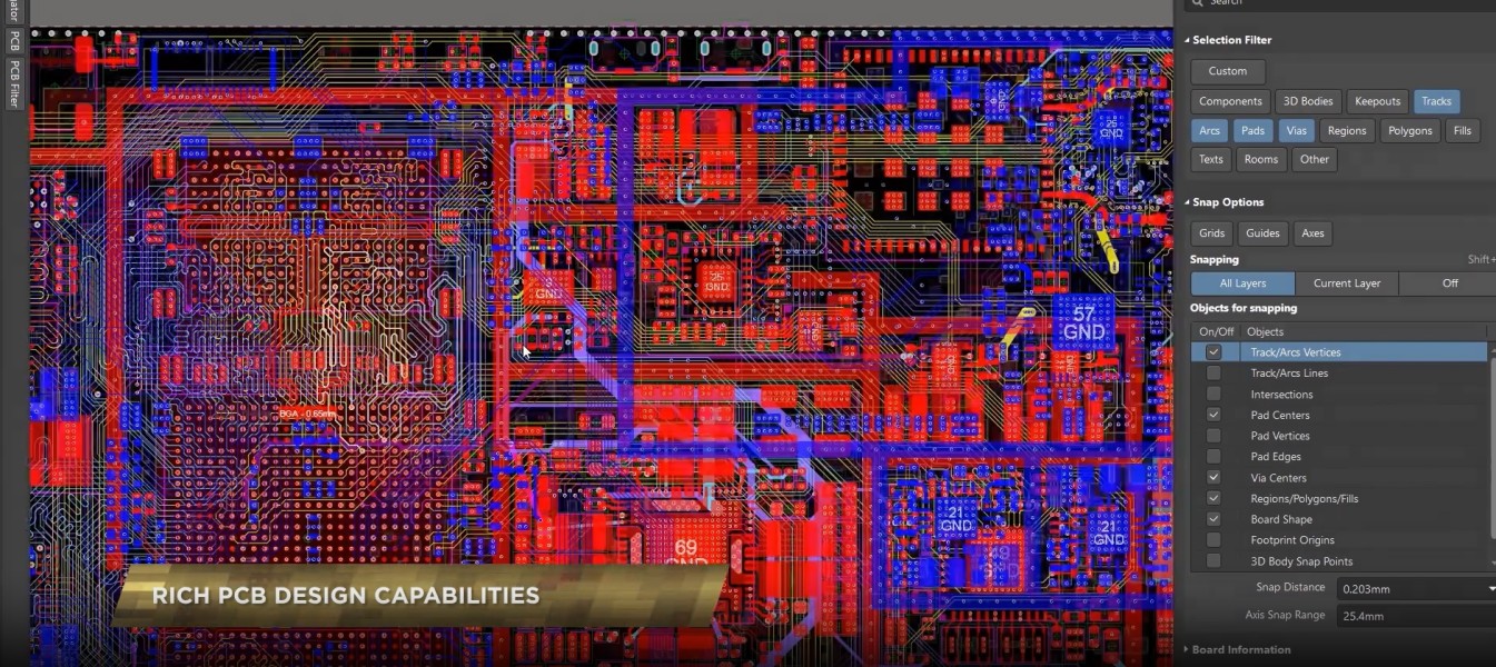
Before making the PCB, electronic design automation (EDA) software, such as Altium Designer, Cadence Allegro, etc., can be used for design verification. These software often have circuit simulation capabilities that can help you simulate and analyze the performance of your circuits to ensure they meet design requirements.
Schematic Check:
Before you start wiring, carefully check the circuit connections and component selections in the schematic. Make sure there are no wrong connections, missing components, or other common design issues.
Layout and Routing:
Before proceeding with layout and routing, review PCB design specifications and constraints to ensure that dimensional, electrical, and mechanical requirements are met. Placement and routing software, such as Altium Designer, Cadence Allegro, etc., can help you complete the placement and routing process.
Electrical testing:
After the PCB is manufactured, test instruments, such as multimeters, oscilloscopes, logic analyzers, etc., can be used to conduct electrical testing on the circuit. These tests can include checking supply voltages, signal waveforms and timing, etc.
Functional Test:
Connect the PCB to appropriate external devices or test equipment and perform a functional test. This can involve sending and receiving data, controlling peripherals, or performing other specific functions. Based on your design needs, you can choose the appropriate test method and equipment.
As for the best testing software, it depends on your needs and preferences. There are many different PCB testing software available on the market, such as NI Multisim, LabVIEW, CircuitStudio, etc. The best option is decided based on your specific requirements and budget. You can refer to the recommendations of other engineers and professionals to compare and evaluate software to find the testing software that is right for you.